How it came to be:
NOTE: If you wish you may go to my original website where you will find the detailed Rowing Page and, in addition, the fluid flow application Streamlines and the ASME 1967 Tables of The Thermodynamic Properties of Steam and Water.
Rowing was big at Cornell when I was there as a student in the late 1940s, as it had been previously at the turn of the 20th century. My parents, both Cornellians of that era (Class of 1912 and Class of 1918), spoke fondly of the winning crews of yore and of their legendary coach Charles E. “Pop” Courtney. And so we modern students paid enough attention to Cornell rowing to have often watched the races on Cayuga Lake and to have had time to observe the rhythm of the stroke.
As a student in Mechanical Engineering and, more particularly in Fluid Mechanics, I often puzzled over the vagaries of the motion of the shell. It is noticeably uneven. In the drive, as the crew applies effort to the oars, the boat seems counter-intuitively to slow only to leap ahead again as the oars and rowers return for the next stroke. This is not an illusion. The shell is feather-light compared to the weight of the crew so that as they propel their mass stern-ward in the reach for the next catch the boat is sent sharply in the opposite (bow-ward) direction.
It is well known in fluid dynamics that the power required to maintain a boat’s motion against fluid friction increases as the cube of boat’s speed through the fluid. Thus, the energy expended to maintain a high velocity for a time can never recovered in the same time spent maintaining a lower velocity.
So, for the same amount of effort, how much faster might a racing shell go if its velocity were somehow kept constant?
As I discovered in later years finding the answer is a daunting task if all you have at your disposal is a pencil, a slide rule, and a piece of paper. Every year or so I would cast my mind back over this problem, sit down in a comfortable chair with my rudimentary tools and have a go at it. My calculus being by then sufficiently rusty meant that even writing down the basic equation of motion for the shell/rower system was an uncertain task. And so I would abandon the effort for better luck another time.
As time went on I had various occasions to dip into the calculus for my career engineering work and in 1964 I discovered the computer—a behemoth known as the CDC 6600 [1] occupying an entire floor of a large building on Boston’s miracle circumferential highway: Route 128. I bought a copy of Daniel D. McCracken’s a guide to FORTRAN IV programming and taught myself to write code. It helped that I was, by then, in the computer division of my employer’s consulting engineering firm. Eventually I became a half decent programmer thanks, in part, to Edsger Dijkstra’s GOTO dictum.
After retirement in 1994 I ran across an article [2] about a new competitive oar blade design that seemed to be winning races: “Just two years ago top college crews were winning races in … five minutes and 45 seconds. [Today] that time has dropped [by] 15 seconds.”
And at about this time (1995) I had a single shell in temporary “storage” in my yard—a birthday gift from a friend to his wife. I was inspired to measure it up for a potential computer description. I realized that now I could assign pencil, slide rule, and paper operations to a machine and so I returned at last to the rowing problem.
First I made a schematic diagram and then worked out a force balance and the differential equation of motion involving the excursions and velocities of the separate masses of crew and boat. From my professional days I had inherited an extensive library of indispensable FORTRAN routines greatly simplifying the writing of code for a great variety of useful functions related to data entry, reading, and checking; sorting; interpolation in data sets; and the control of organization and pagination in final output printing—so-called “housekeeping” routines.
Next, for rowing eights, I designed a seating arrangement that would permit a crew to make eight individual strokes in sequence without physical interference in the boat. Sequential strokes were essential to the aim of reducing the large velocity excursions to eight smaller “ripples”. This new geometry required a slight lengthening of the shell from its traditional sixty-two foot base. In practice it would also require the coxswain to broadcast a “beat” to a headset worn by each rower so that each had his own private stroke timing.
After several months enough code had been written to permit the production of rudimentary graphs of speed, forces, and motion depending on a very large number of input variables. Ultimately the model had more than eighty input variables having to do with boat, oar, and rower characteristics, environmental data (wind speed, water temperature, etc.), initial conditions, and the lift and drag characteristics of oar blades. The model currently has many thousands of lines of code and is still a work in progress.
The rower has two points of force contact in the dynamic system—at the oar handle and at the footstretcher. With one exception [3] no rowing modeler had previously considered forces at the rower’s feet in relation to their possible effect on the net advancement of the shell. The forces there are as large as those at the oars. They produce the large shell excursions seen. But, because nothing other than fluid friction connects the boat to the water (no “blades” involved), the net effect on speed was, I think, assumed to be nonexistent or too small to be of importance.
The program divides the stroke into one-thousand increments each of which is calculated in sequence and then repeated (iterated) with re-adjusted starting conditions until the calculated shell advance per sweep is equal to the theoretical (geometric) advance—often a process of more than a hundred iterations. In addition the shell speed at stroke’s end had to be continuously adjusted to equal that at the beginning. In 1996 when I started coding on my PC this process took agonizing and frustrating minutes per iteration. Today one thousand “external” iterations (plus many hundreds of thousands of internal ones) are completed virtually instantaneously.
It turned out to be too daunting to write code for eight separate rowers whose strokes were offset with respect to one another by one eighth of the cycle. But I finally hit upon the way to model a shell speed with constant velocity—my initial aim. It was as simple as assigning a near infinite inertial mass to the shell (its speed can’t be changed no matter what the size of the forces on it) but without changing its displacement or the hydrodynamic resistance forces—something a program is eminently capable of doing.
The result was surprising. The average shell speed for the same rower power expenditure was less than that with the original shell speed excursions. The net work done on the boat at the foot board at the varying speed turned out to be positive and not to be done without. A related observation: I think if one sits in a shell (no oars) and shifts his weight, quickly one way and slowly the other the shell will (very inefficiently) advance in response to the quick effort. Children commonly can do this in go-carts, which have greater friction effects than does a boat on water.
So, I had answered my question. In rowing there is virtually nothing to be gained by eliminating the velocity excursions of the shell.
But there were other things to ponder. Now that I had a working model I decided to improve it to a point where it might actually be of use to rowers [4]. Too, there was much rowing lore and conventional wisdom to look into, some of which confused and baffled me for long periods of time.
Rowers spoke of the various effects of this or that on the “force at the blade”; things like the blade’s size or its efficiency, or the degree to which it was submerged, or the lever ratio (“gearing”). In fact, I finally realized that the force at the blade is nothing more than the result of its balancing the rower’s effort at the handle, having nothing whatever to do with the blade’s shape or size.
It took ages to resolve the mystery of oar blade slip in the water. Observed from above, as from a bridge, the blade seems to leave the water at almost exactly its entrance point—it doesn’t seem to slip at all. What was happening? I fixed a rectangular board to the end of a broomstick “foot-wise”, noted its area, weighted it a known amount, and timed it as it sank a measured vertical distance in a deep pail of water. Crude to be sure, but the result of calculation from the known resistance to flow of flat plates told me that oar blade slip must be hugely greater than anyone seemed to think. But, how was I to determine it? There’s no fixed catch reference point left behind in the water.
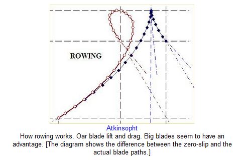
Then I saw that a blade with no force on it was the only condition under which its slip could be zero. What is the path of an unloaded oar blade? All one has to do, from a coasting shell, is to drop the blade into the water and let it drift freely stern-ward. The drifting blade center follows a path well known in analytical geometry—the tractrix. And thus the mathematical solution of the path of the tractrix enables one to find the true blade slip which, in practice, is huge—as much as a meter in many cases. The slip is the longitudinal separation between the actual blade path and the zero-slip path.
The simple tractrix is the path of a straight, flat blade—one without a cant angle or “spoon”. The conventional six-degree canted blade follows a modified path that I have chosen to call an “oblique” tractrix. Unfortunately the solution to the differential equation for this path was not direct (it involved arc functions) and had to be iterated by trial and error using Euler’s modified method.
Working out the complex vector diagrams of the blade forces and velocities was difficult owing to the dynamic nature of the lift and drag forces. The slip of the blade depended upon the lift and drag forces which, in turn, depended upon the slip and so yet another iterative process was introduced to solve every instant of the stroke. My general “take away” from all of this is that “Nature is inherently iterative”.
I chose, too, to iterate (by Euler’s method) the main solution to the equation of motion, although this is not required; a direct solution involving the velocity squared is easily made. My reasoning was that I was not entirely sure that the valid velocity exponent is an integral 2. Many hydrodynamic relationships use an exponent near two (1.85 for instance) and in trying to see whether ROWING would produce the same or similar performance as some real world data sets that I had available (from Kleshnev [3]) I thought to see whether exponent changes might account for interesting differences. The velocity exponent is part of my input data set. There is no way of dealing with non-integer equation of motion exponents without an iterative process.
Eventually I discovered others who had written a comprehensive rowing model. One, in MatLab, is Marinus van Holst of the Netherlands [5]. Among other things he and I once agreed on a data set with the same content for each model and showed that each produced almost the same result in speed and rower effort; a strong indicator of the validity of each model. Others are Sander Roosendaal [6] and Leo Lazauskas [7].
The drive has three phases: force buildup, force variable, and force declining which can be defined in terms of straight lines defining absolute force and force duration.
I divided the stroke into eight “regimes”, four in the drive phase (including the arms bend) and four in the free return permitting study of various patterns of slide and torso motion: pause, onset, steady, and close. Thus, especially, the free return can seem to be “coached” in its four phases. However, contrary to the conventional wisdom, the model shows that nothing one can do in the free return can directly alter the (average) speed of the center-of-mass of the boat-rower system. Nevertheless, it is possible to save some small amount of energy in the free return—by encouraging “float”— which could be used elsewhere as slightly increased stroke rate or greater effort at the oars, but without increase in total effort.
Since, on average in the steady state, the shell is not accelerating it must be that the instantaneous forces on it sum to zero over the stroke. This requirement is a powerful check on the accuracy of the computations. The same is true of the reaction forces on the body of the rower.
Much was made in the rowing literature of the supposed beneficial effect of hydrodynamic lift, but I could not envision clearly how this might operate on a surface with such wild variations in angle of attack as compared with the relatively stable airplane wing.
The lift and drag characteristics of an oar blade have no more effect on the rower’s propulsive force than the lift characteristics of a wing have on the weight of an airplane. Lift and drag are important only insofar as they affect inefficient blade slip. And, in this regard, drag rules.
One aspect of the work done by a rower (or any athlete) is the work done on his or her own body—what I call the internal energy. It is the work done (above resting metabolism) to warm and tire the muscles, and to increase the breathing and heart rates. There seem to be many, especially in the world of rowing ergometers, who do not take this effort into account—it doesn’t (can’t) show up on the erg display or in its calculator. It seems to me that if a rower on an erg were to urge himself forcefully back and forth with his leg and torso muscles (feet in stretchers and without the fan wheel handle) he would soon tire. Its calculated value in ROWING is not inconsequential, maybe as much as twenty percent of the rower’s total output. The model calculates it and adds it to the rower’s total effort where it shows up in total rower power and efficiency.
In general the model seems to show that a trade-off between stroke rate and rower work, in which increasing effort at the expense of stroke rate (at equal total rower power), is advantageous. This shows up in several ways. In its simplest form—simply pull harder (but less often) at a reduced rating—it is analogous to shifting a car into higher gear. Also it can be achieved by small increases in oar lever ratio in order to decrease rating without pulling any harder. Furthermore, my pages at oarlngth.htm and at forcratg.htm show that high (“stiff”) lever ratios can be advantageous. Much points toward pulling a bit harder and easing up on the stroke rate [8]. It might be a good thing if, during a race, a rower could easily vary his lever ratio; high for a tail wind, low for a head wind; low for the starting strokes and high for winning in the long haul.
The model indicates, too, that narrowing the angle between oar and shell at the catch can help; and puts to rest the myth of the dangers of the “pinch point”. Catch (bow) angle can be reduced by rigging “through the work” (sculls) or by changing the cant angle of the blade (sweeps). See bladangl.htm. Dreher at Durham Boat [9] did some experimenting with negative sweeps cant angle but was unable, I think, to put into it the immense and chancy effort required to prove the idea.
The advantage of large blade surface area [bladarea.htm] seems so clear that I am baffled as to why area has not increased since the introduction in 1994 of the “Big Blade.” Blade slip is the single most important variable in the definition of blade efficiency—slip decreases markedly with area increase. To be sure, at the same lever ratio, a big blade feels “heavier” than a smaller one, but it is all a part of the same idea of pulling with the same force at a reduced rating. I think blade makers err in increasing area and then, at the same time, turning around to reduce the lever ratio so that the oar again “feels” more like what rowers are used to. The reduced ratio simply reintroduces the unwanted slip that the area increase was to have reduced. Obviously, of course, there is an area too large for any rower to deal with, but I don’t think that point has yet been reached.
If a rower wants seriously to go faster he will have to train himself to accept and to perfect performance with a new and unfamiliar “feel,” whether it is the result of a better blade or of a new, more deliberate style.
There is, on the Web, a “meta” rowing site–“The Top One-hundred”–comprising some eight-hundred individual sites, sorted in order of “click” popularity.
On a personal note:
My ROWING website at http://www.atkinsopht.com will not be “up” forever. It has now been on the Web for almost fifteen years. I am ninety-eight years old and the time will soon arrive whereon I will no longer be able to maintain the site, nor to answer the many interesting queries I receive in my e-mail at Atkinsopht@Gmail.com. My best wishes to all of the many who have shown an interest in this site.
It can always be found on the WayBack Machine.
References:
[1] CDC 6600: https://en.wikipedia.org/wiki/CDC_6600#Operating_system_and_programming
[2] Langston Gantry Jr., “The Technology Crew”, Cornell Magazine, June, 1994.
[3] Valery Kleshnev: http://www.biorow.com His work is valuable because of its empirical nature; much harder to make lab and field measurements than to make computer computations.
[4] The ROWING abstract: http://www.atkinsopht.com/row/rowabstr.htm
[5] Marinus van Holst: [I am sorry to report Marinus’ recent death: (12/2019)]
His site has been preserved.
[6] Sander Roosendaal: SanderRoosendaal.wordpress.com
[7] Leo Lazauskas: https://www.boatdesign.net/threads/free-internet-rowing-model-2-32-released.52866/
[8] Brown, Daniel J., “The Boys in the Boat”, Penguin, 2014 (Paperback) pp. 99, 105, 116, 168, 247, 254. The author’s race histories (if accurate) seem to support this idea—slow and strong beats fast and furious.
[9] Dreher Oars: http://www.durhamboat.com/oars
Library of graphic files for inclusion in Web posts:
Instant Center- outboard

I have added your link. Thanks for passing it on to me.
LikeLike
Guus:
I will happily add a link to the work of Marinus.
Bill
LikeLike
Dear mr. Atkinson,
Here you can find the saved Rowing model of Marinus van Holst. https://teunispolak.github.io/home.hccnet.nl/m.holst/RoeiWeb
I hope you can make this link available in your very interesting rowing model. Thank you very much.
Guus van de Beek
gvdbeek@caiw.nl
LikeLike